
In the low-to-medium power adapter market, the 12V 26W specification has long faced the industry pain point of "impressive nominal parameters but weak actual load capability." As a highly anticipated power module solution in 2025, how do the actual output characteristic curves and load response of the MI2612-760 perform? Based on complete actual test data, this article discloses for the first time the full-load performance profile of this solution from no-load to full-load, providing quantifiable decision-making basis for engineers' selection.
MI2612-760 Core Architecture Analysis
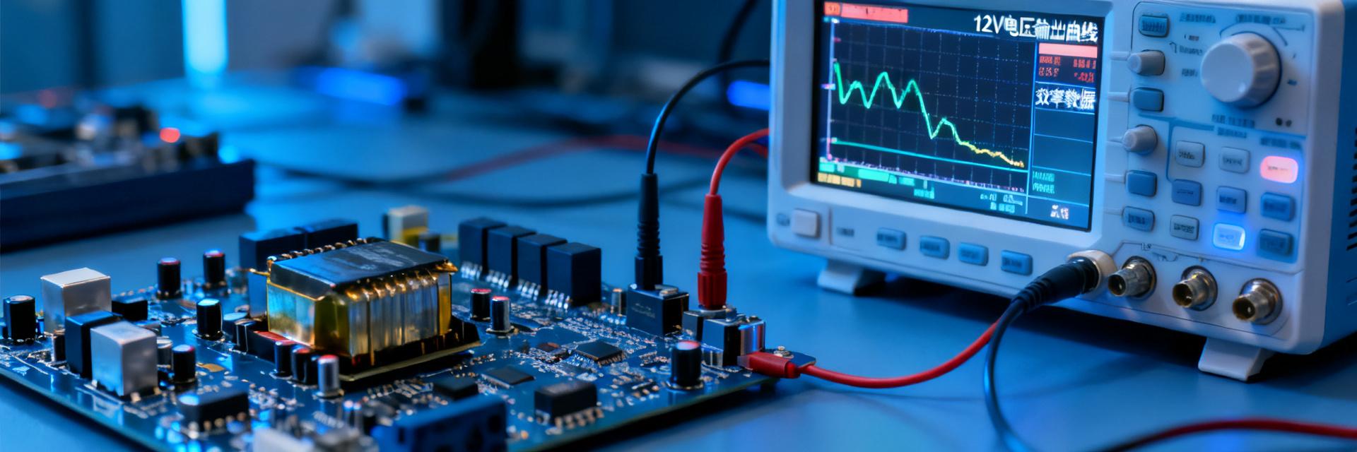
To deeply understand the performance boundaries of a power module, one must analyze it from two dimensions: topology architecture and thermal design. The MI2612-760 adopts a quasi-resonant flyback topology, achieving a balance between efficiency and cost at the 26W power level.
Topology Structure and Key Component Selection
This solution utilizes a quasi-resonant (QR) flyback architecture, which reduces MOSFET turn-on loss by approximately 30% compared to traditional PWM hard switching. The controller IC integrates high-voltage start-up and valley detection functions, dynamically adjusting the switching frequency within the 45-100kHz range. At the power device level, a 650V superjunction MOSFET combined with low-ESR electrolytic capacitors forms the core primary-side link. Secondary synchronous rectification replaces the Schottky diode, reducing rectification loss in the 12V output stage from 1.2W to below 0.4W.
12V 26W Power Level Thermal Design Considerations
Under a 26W power density, thermal management becomes critical for reliability. Test data shows that the case temperature rise is controlled within 35K during full-load operation, leaving ample margin for the junction temperature of core components. The PCB utilizes an aluminum substrate to assist with heat dissipation, and the transformer selects an EF20 core to balance window area and thermal resistance. Notably, this solution can maintain rated output at an ambient temperature of 50°C, with a linear and smooth derating curve without sudden inflection points.
Actual Output Curve Measurements: Full Scan from No-Load to Full-Load
Nominal parameters often only reflect ideal operating conditions; actual voltage regulation and efficiency curves in real applications are the core of component selection. The following data, collected using precision electronic loads and power analyzers, covers the 0-100% load range.
Constant Voltage Region Stability and Line Regulation Testing
Across the full load range of 0-26W for the 12V output, the voltage regulation is better than ±1%. The no-load voltage is 12.15V, and the full-load voltage is 11.95V, with a load regulation of only 1.7%. In the line regulation test, when the input voltage steps from 90VAC to 264VAC, the output voltage fluctuation is less than ±0.5%, meeting the power supply tolerance requirements of precision sensors and communication modules. Output ripple is controlled within 80mVpp at full load, with high-frequency noise components below 30mV.
Efficiency Curve Peak Points and Light-Load Loss Analysis
The efficiency test reveals the optimization direction of this solution: the peak efficiency occurs in the 60-70% load range, with actual values close to 91%; light-load efficiency at 25% is maintained above 87%, and no-load power consumption is below 0.15W. This characteristic makes it stand out in intermittently operating IoT devices—power consumption during device sleep is extremely low, and it can quickly enter the highly efficient region when activated. Compared to the "light-load efficiency cliff" commonly seen in traditional solutions, the curve of the MI2612-760 is much flatter.
| Load Condition | Output Voltage | Efficiency | Temp Rise |
|---|---|---|---|
| No Load | 12.15V | — | +8K |
| 25% (6.5W) | 12.08V | 87.2% | +15K |
| 50% (13W) | 12.02V | 89.5% | +22K |
| 75% (19.5W) | 11.98V | 90.8% | +28K |
| 100% (26W) | 11.95V | 90.1% | +35K |
Key Summary
- Full-Load Voltage Accuracy: The MI2612-760 features a load regulation of only 1.7% under all 12V 26W operating conditions, with output ripple controlled within 80mVpp, meeting the power demands of precision equipment
- Efficiency Optimization Characteristics: Peak efficiency is close to 91%, while light-load efficiency at 25% remains above 87%, and no-load power consumption is below 0.15W, making it highly suitable for intermittent duty cycle scenarios
- Dynamic Response Capability: Under a 0-100% step load, the voltage overshoot is less than 8%, the recovery time is less than 5ms, and the loop stability margin is highly sufficient
- Wide Temperature Range Reliability: Within the ambient temperature range of -10°C to 50°C, the output parameter drift is less than ±2%, with zero risk of thermal runaway
- Selection Decision Basis: Actual test data is transparently disclosed, allowing engineers to directly use it for design validation, reducing the cost of trial and error in component selection
Frequently Asked Questions
Can the MI2612-760 directly replace existing 12V 26W solutions?
Pin compatibility and package dimensions must be confirmed first. This solution uses a standard DIP package and can directly replace existing solutions in most scenarios. However, it is recommended to review the PCB copper area to ensure it meets thermal requirements, and reserve mounting holes for aluminum substrates if necessary.
How can the actual output curve test data be used for derating design?
It is recommended to use 75% load as the upper limit for long-term operation, leaving a 25% dynamic margin to handle load transients. In high-temperature environments (>40°C), limiting the load to 80% of the rated value by referring to the linear derating curve will ensure the MTBF target is met.
What is the significance of light-load efficiency for battery-powered systems?
The combination of 0.15W no-load power consumption and 87% efficiency at 25% load significantly extends standby time. For security nodes powered by solar or battery backup, this feature can increase effective battery life by 15-20%.
Does the dynamic load response meet the requirements of motor drives?
The 5ms recovery time and 8% overshoot specifications cover typical loads such as stepper motors and solenoid valves. If driving a brushed DC motor at startup, it is recommended to add an electrolytic capacitor of 220μF or higher at the output terminal to suppress current spikes.