
In the compact design of industrial distribution cabinets and automation control cabinets, 35% of electrical failures stem from improper terminal block installation. As a dedicated carrier for 10-conductor connectors, how does the WAGO 221-539 mounting carrier precisely match DIN-15 rails and achieve reliable fixation? Based on the latest technical parameters, this article systematically analyzes the core points of selection and installation.
Product Positioning and Technical Specifications Overview
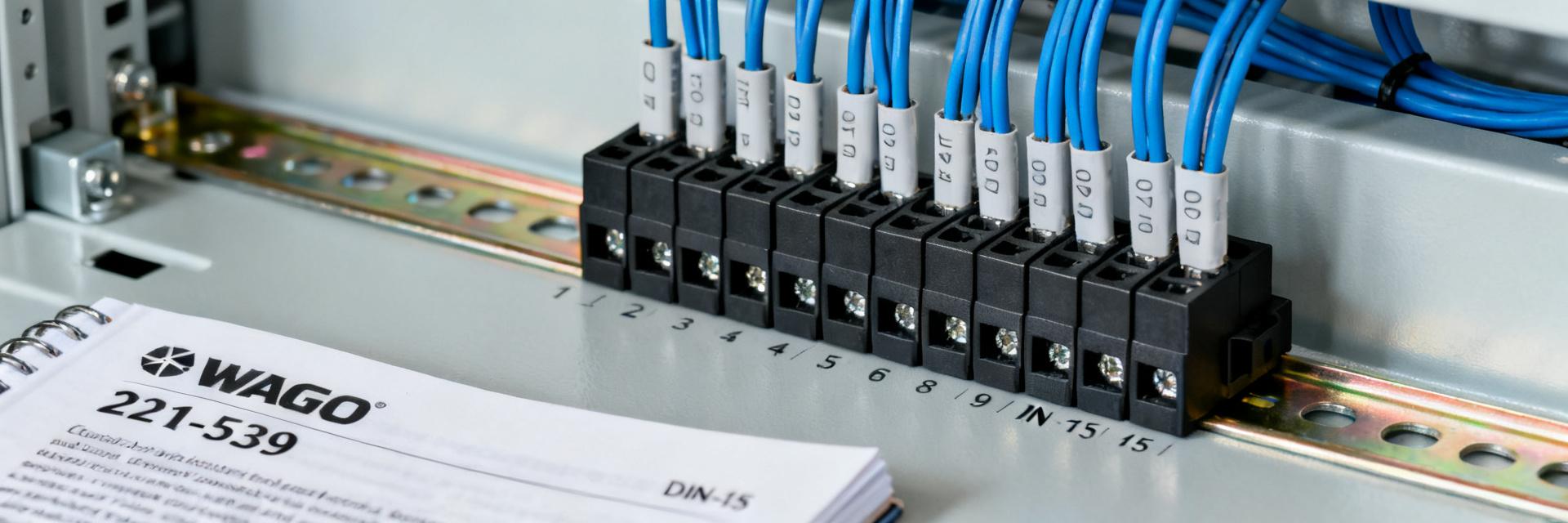
The 221-539 is a standardized mounting carrier designed specifically for 221 Series 10-conductor connectors. Its core mission is to transform scattered wire connections into modular, maintainable cabinet assembly solutions. The carrier is made of Polyamide 6.6 (PA6.6) material with a UL 94 V-0 flammability rating and a wide operating temperature range from -40°C to +85°C, meeting the requirements of most industrial environments.
Interpretation of 221-539 Core Parameters
The carrier body width is 105mm, height is 47mm, and depth is 62mm, accommodating up to ten 221 Series 4mm² connectors mounted side-by-side. The key design highlight lies in the dual-sided snap structure—the bottom latches with the DIN-15 rail, while the top secures the connector body via elastic arms. The rated current carrying capacity reaches 32A with an insulation voltage of 400V, compliant with the IEC 60947-7-1 standard.
Regarding version differentiation, the 221-539 has several suffix variants: the basic type (1000-000) features an open design; the 1002-000 version integrates a protective cover with an IP20 protection rating to guard against finger contact; and the 002-000 is a white marking version for easy phase differentiation. Selection should be comprehensively determined based on the cabinet protection rating and maintenance frequency.
Compatibility with 221 Series 10-Conductor Connectors
A 10-conductor connector (such as the 221-685) has a width of 9.5mm per pole, with a total 10-pole width of 95mm. The 105mm inner cavity of the 221-539 reserves appropriate tolerances and heat dissipation gaps. During installation, the connector is pressed vertically from the top until a "click" sound indicates it is locked in place. During removal, both sides' release levers must be pressed simultaneously to avoid latch fatigue caused by forced extraction.
| Parameter | 221-539 Carrier | 221-685 Connector |
|---|---|---|
| Rated Current | 32A (Carrier) | 32A |
| Applicable Wire Cross-section | - | 0.14-4mm² |
| Mounting Method | DIN-15 Rail Snap-in | Carrier Plug-in Type |
| Flammability Rating | UL 94 V-0 | UL 94 V-0 |
DIN-15 Rail Selection and Compatibility Analysis
DIN-15 rails (EN 60715 standard) are fundamental components of industrial control cabinets, and their quality directly determines the long-term stability of the carrier system. The rail compatibility design of the 221-539 reflects the precise tradition of German engineering.
DIN-15 Rail Dimensional Standards and Tolerance Requirements
Standard DIN-15 rails have an "Ω"-shaped cross-section, with a top width of 15mm, a height of 5.5mm, and bottom widths typically available in 7.5mm (light duty) and 15mm (heavy duty) specifications. The clamping mechanism of the 221-539 fits the 7.5mm bottom-width standard type, with a designed clamping force of 120N±20N—sufficient to resist cabinet vibration while facilitating subsequent maintenance and disassembly.
Rail length selection follows the "n+2" principle: total connector width + 50mm margin on each end. For example, ten 221-685 connectors require 950mm of space, so a 1050mm rail is recommended. If a layered layout is used, the recommended layer spacing is ≥80mm to ensure operating space and heat dissipation channels.
Impact of Rail Material on Mounting Stability
Galvanized steel rails are low-cost but prone to corrosion, making them suitable for dry environments; aluminum alloy rails reduce weight by 40%, though electrical conductivity must consider grounding continuity; the stainless steel 316L version is designed specifically for coastal or corrosive chemical environments. When the polyamide latch of the 221-539 mates with metal rails, the friction coefficient remains stable in the 0.25-0.35 range, preventing "creeping" or loosening.
Comparison of Mounting Methods: Snap-in vs. Screw Fixation
The 221-539 provides two fundamental methods for fixing to the cabinet: the quick-mount snap-in scheme on rails, and the alternative path of direct screw fixation. Understanding their mechanical differences is key to avoiding on-site rework.
Operational Flow and Precautions for Quick Snap-in Installation
The standard process is: pre-install the rail → tilt the carrier at 15° to snap it in → press down to lock horizontally. During operation, confirm the "double click" feedback—the first click is the bottom hook engaging, and the second click is the top limit slotting into place. Common mistakes include: rail edge burrs causing biased latch loading, and lack of positioning templates during multi-layer installation leading to cumulative errors.
For vibration environments (such as rail transit, marine), it is recommended to add anti-loosening measures: apply thread locker to the contact surface between the rail and the carrier, or choose a heavy-duty rail version with elastic washers.
Applicable Scenarios and Torque Specifications for Screw Fixation
When the cabinet lacks standard rails or requires suspended mounting, the 221-539 base reserves M4 screw holes. The installation torque is strictly limited to 1.2-1.5 N·m; over-torque will cause polyamide creep cracking, while under-torque will trigger fretting wear. It is recommended to use a torque screwdriver with a Phillips bit to avoid the impact loads of pneumatic tools.
Typical Application Scenarios and Configuration Schemes
The value of the 221-539 is fully realized under tight spatial constraints, with the following two scenarios being the most representative.
Multi-Layer Layout Design in Compact Distribution Cabinet Spaces
In a standard 600×600×200mm distribution cabinet, using the 221-539 allows for a high-density three-layer layout: each layer accommodates 10 connectors, requiring only 90mm of vertical space for 30 control circuits. Compared to traditional terminal blocks, this saves about 35% of space in the depth direction. A key technique is to use a "zigzag" wiring pattern—odd layers route wires to the left, even layers to the right—to avoid wire crossover interference.
Special Installation Requirements under Ex Explosion-Proof Environments
According to the IEC 60079-7 increased safety equipment standard, when the 221-539 is used in Zone 2 areas, it must meet the following: the protective cover must be completely closed, the wire strain relief device must be ≤150mm from the connector inlet, and the spacing between adjacent carriers must be ≥3mm to prevent heat accumulation. It is recommended to choose the 1002-000 protective version and pair it with increased-safety cable glands to form a fully sealed system.
Selection Decision Checklist and Avoidance of Common Pitfalls
A systematic selection process can reduce design errors by more than 60%.
5-Step Quick Selection Method: From Connector Count to Rail Length
- Count the number of single-point connectors and round up to the nearest multiple of 10
- Determine protection requirements: open / covered / transparent cover
- Calculate rail length: total connector width + 100mm margin
- Verify current-carrying capacity: 32A is the hard upper limit, leave a 20% derating margin
- Confirm environmental suitability: temperature, flammability, IP rating
3 Major Installation Pitfalls: Missing Strain Relief, Insufficient Spacing, and Material Mismatch
Missing strain relief: The gravity of the wires acts directly on the connector terminals, leading to increased contact resistance over time. Cable tie fixing points must be provided on both sides of the carrier.
Insufficient spacing design: When the center distance between adjacent 221-539 carriers is <120mm, the space for tool operation is limited, and maintenance efficiency drops sharply.
Material mismatch: Using the 221-539 in direct outdoor sunlight without selecting a UV-stabilized version will cause the polyamide to pulverize and embrittle within six months.
Key Takeaways
- The 221-539 is designed specifically for 221 Series 10-conductor connectors, providing a standardized DIN-15 rail mounting solution with a rated current of 32A
- DIN-15 rail selection must focus on the 7.5mm bottom-width standard, galvanized/aluminum/stainless steel material matching, and the "n+2" length planning principle
- Snap-in mounting prioritizes efficiency, while screw fixation handles special scenarios; controlling torque to 1.2-1.5 N·m is a critical quality point
- A three-layer zigzag layout is recommended for compact distribution cabinets. Ex environments must use the protective cover version and meet increased safety spacing requirements
- Strain relief, operating clearance, and material weatherability are three key design inspection items to prevent on-site failures
FAQ
Can the 221-539 be compatible with 10-conductor connectors from other brands?
The plug-in interface of this carrier strictly matches the physical dimensions and locking mechanism of the 221 Series connectors. While third-party products meeting the same mechanical interface specifications might physically fit, electrical safety certifications must be evaluated independently, and mixing brands is not recommended.
Are DIN-15 and DIN-35 rails interchangeable?
No, they are not directly interchangeable. The clamping mechanism of the 221-539 is designed specifically for a 15mm top-width rail. Forcing it onto a 35mm rail will cause the latch to fail. If the project strictly requires a 35mm system, compatible models such as the 221-549 must be used.
Does the protective cover version affect connector heat dissipation?
The enclosed structure of the 1002-000 version increases the temperature rise by approximately 5K compared to the open design, but it remains well below the material's maximum temperature limit under the 32A rated operating condition. For continuous operation under high loads, a 10% current derating is recommended, or a ventilated cabinet design should be used.
Are there functional differences between the carrier color versions?
The 002-000 white version is purely for visual phase differentiation; its electrical performance is completely identical to the basic black version. In three-phase systems, it is recommended to use yellow for Phase A, green for Phase B, and red for Phase C, with white for the neutral wire and green-yellow for the ground wire.