
As the demand for position detection accuracy continues to rise in industrial automation and consumer electronics, TMR (Tunneling Magneto-Resistance) switch chips are accelerating their replacement of traditional Hall devices thanks to their dual advantages of ultra-low power consumption and high sensitivity. Data shows that in battery-powered applications, the average current consumption of TMR magnetic switches can be as low as 160 nA at 3.0 V, nearly an order of magnitude lower than conventional solutions—this figure marks a pivotal turning point as magnetoresistive sensing technology transitions from the laboratory to large-scale commercial use.KTM1321XAAs one of the most closely watched models in this series, its core specifications in the datasheet directly determine the success or failure of component selection. This article will take the datasheet as a blueprint and break down each parameter item by item.KTM1321XAto help you make precise decisions during the selection and design phases.
Technical Background of TMR Switch Chips and the Positioning of KTM1321XA
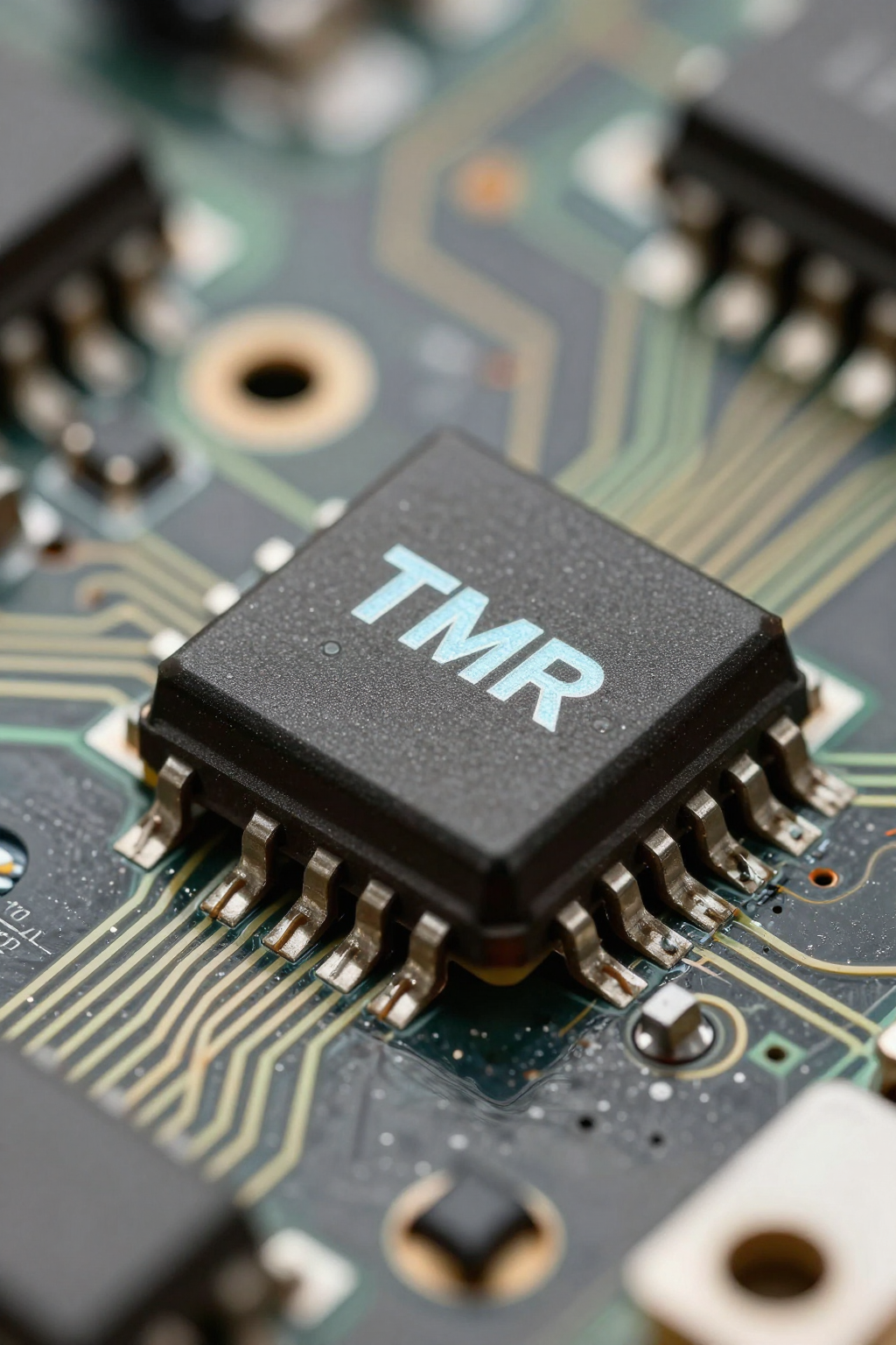
From Hall Effect to TMR: The Generational Evolution of Magnetic Switch Technology
The technological evolution of magnetic switch chips has progressed clearly from the Hall effect to AMR, GMR, and finally TMR. Although Hall devices are mature and inexpensive, their sensitivity is limited and power consumption relatively high. AMR and GMR offer improved sensitivity but remain constrained by a narrower linear range. TMR technology, leveraging the tunneling magnetoresistance effect, achieves a greater change in resistance under the same magnetic field, thus providing higher sensitivity, lower power consumption, and a wider operating temperature range. This generational advantage is precisely what you need to understand.KTM1321XAThe parameter system serves as a technical coordinate system—its nanoampere-level power consumption and stable magnetic field threshold performance are not isolated metrics, but rather direct manifestations of the benefits brought by TMR technology.
The Role of KTM1321XA in the TMR Switch Chip Series
Based on the datasheet positioning,KTM1321XAThe distinguishing features of this TMR switch chip among its peers are mainly reflected in its operating mode and package type. It is designed for typical low-power position-sensing applications, making it suitable for battery-powered portable devices and industrial nodes that require long-term maintenance-free operation. When selecting a model, you should first verify whether the latching or bipolar operating mode matches your magnet's motion pattern, then consider the package size to determine if it can fit into your existing structural space. This quick identification method helps you quickly narrow down the candidates from among the many models in the series.
Detailed Analysis of the Core Electrical Parameters of KTM1321XA
| Parameter Item | Typical Value/Range | Engineering Significance |
|---|---|---|
| Operating Voltage (VCC) | 1.8V ~ 5.5V | Compatible with lithium batteries and industrial power rails, eliminating the need for additional voltage regulation |
| Average Power Consumption (50Hz Version) | 160 nA @ 3.0V | Ultra-low power consumption, ideal for battery-powered devices with long endurance |
| Average Power Consumption (Continuous Version) | 1.9 µA @ 3.0V | High-speed response, suitable for real-time monitoring scenarios |
| BOP (Operating Point) | Depends on the specific model | Minimum magnetic field strength required to turn on the switch |
| BRP (Release Point) | Depends on the specific model | Maximum magnetic field strength at which the switch turns off, creating hysteresis |
Operating voltage range and power consumption characteristics
According to the datasheet data,KTM1321XAIt features a typical wide operating voltage range of 1.8V to 5.5V, enabling compatibility with both single-cell lithium battery power supplies and industrial 3.3V/5V power rails, while maintaining stable operation without the need for additional voltage regulation. In terms of power consumption, the 50Hz version and the continuous-operation version differ significantly: the former achieves an average current as low as 160nA at 3.0V, whereas the latter consumes around 1.9uA at 3.0V. For portable devices where battery life is a key metric, the 50Hz sampling version is the preferred choice; meanwhile, for high-speed applications requiring real-time continuous monitoring, the continuous-operation version trades higher power consumption for uninterrupted response. You should weigh these two options based on your system's specific sampling requirements.
Magnetic field threshold parameters: Engineering meanings of BOP and BRP
In the datasheet, BOP (Operating Point) and BRP (Release Point) are core parameters that determine the consistency of switch operation. BOP refers to the minimum magnetic flux density required to enhance the magnetic field and turn the switch on, while BRP is the threshold at which the magnetic field weakens enough to turn the switch off. The hysteresis between these two points (BOP−BRP) provides anti-dithering capability. When designing magnet selection and air gap, you must ensure that the actual applied magnetic field can reliably exceed BOP and remain below BRP; otherwise, the switch may fail to trigger or experience repeated toggling. It is recommended to reserve a 20%–30% magnetic field margin in the air gap design and, combined with the magnet's temperature characteristics, verify BOP drift at high temperatures to ensure reliable operation across the entire temperature range.
Detailed Explanation of Output Characteristics and Switch Behavior Parameters
Output Stage Structure and Drive Capability
AnalysisKTM1321XAThe output stage circuit structure in the datasheet determines how it interfaces with downstream circuits. You need to confirm whether the output is push-pull or open-drain: a push-pull output can directly drive an MCU's GPIO and provides a full voltage swing; an open-drain output requires an external pull-up resistor but facilitates level translation and wired-AND operations among multiple devices. When designing the interface, be sure to verify that the output current capability meets the sink/source current requirements of the downstream PLC input module or MCU pins, and confirm that the output high-level voltage is compatible with the target system's logic threshold to avoid misinterpretation due to level mismatch.
Switching Frequency and Response Time
Based on the operating frequency and response time parameters provided in the datasheet,KTM1321XAThe dynamic performance in high-speed position detection scenarios deserves attention. The 50Hz version achieves ultra-low power consumption through intermittent sampling, resulting in a relatively longer response time, making it suitable for applications with low rotational speeds or slow position changes. In contrast, the continuous-operation version offers faster response speeds, capable of capturing rapid flux variations. When evaluating, you should align the system's required maximum detection frequency with the chip's sampling rate. If the magnetic field variation frequency of the measured object approaches half of the sampling frequency, you should upgrade to the continuous-operation version to avoid missed detections.
Extreme Parameters and Reliability Metrics in the Datasheet
Absolute Maximum Ratings and ESD Protection Levels
Breaking down the absolute maximum ratings (voltage, current, temperature) and ESD protection levels in the datasheet is a necessary step to clearly define the design's safety margins. The absolute maximum ratings do not represent normal operating conditions but rather the limits beyond which the chip may be damaged; when designing power supplies, you should ensure that any transients—such as hot-plugging or inductive load kickback—do not exceed these limits. Meanwhile, the ESD protection level directly affects electrostatic risks in both the production line and field environments. It is recommended to add appropriate TVS protection to signal pins during PCB layout and to follow the soldering and handling guidelines specified in the datasheet to prevent chip failure caused by exceeding these limits.
Operating Temperature Range and Long-Term Stability
By combining the industrial-grade and consumer-grade temperature ranges and long-term drift specifications provided in the datasheet, one can evaluateKTM1321XAReliability performance in harsh environments. The industrial-grade version covers a wider temperature range, making it suitable for outdoor equipment, motor control, and other applications; the consumer-grade version is ideal for indoor products with well-controlled temperatures. When making your selection, compare the peak ambient temperature of your target application with the nominal range specified in the datasheet, and allow for an adequate margin. For nodes that require long-term calibration-free operation, also review the long-term drift data in the datasheet to determine whether a periodic self-calibration mechanism should be designed.
Selection and Design Action Guide Based on the Datasheet
Selection Checklist: Five Steps to Confirm Whether KTM1321XA Is a Match
Develop a quick selection checklist based on the datasheet to systematically verify compatibility: First, confirm that the operating voltage range covers your power rails; second, ensure that the BOP/BRP threshold matches your magnet's magnetic field strength; third, check whether the output type (push-pull/open-drain) is compatible with the downstream circuitry; fourth, compare the package size with the available board space; fifth, verify that the operating temperature range encompasses your application environment. Only after passing all five steps should you proceed to the prototype verification stage. If any step fails to match, return to the product series and re-select a suitable model.
Key Design Considerations and Common Pitfalls in Typical Application Circuits
Around the typical application circuits in the datasheet, selecting appropriate peripheral components, arranging magnets, and configuring decoupling capacitors are key design considerations. You should place decoupling capacitors close to the power pins to suppress noise, and when laying out the magnets, strictly follow the induction direction indicated in the datasheet to avoid reversing the magnetic polarity, which could cause the switching logic to flip. Common pitfalls include an air gap that is too large, resulting in an actual magnetic field lower than BOP and thus failing to trigger, or neglecting to verify the magnet's temperature coefficient, leading to failure at high temperatures. It is recommended to measure the actual BOP/BRP trigger points on the first prototype and record the operating thresholds at different temperatures, establishing a baseline for consistent mass production control.
Key Summary
- KTM1321XAIt features a wide operating voltage range of 1.8V to 5.5V, compatible with lithium batteries and industrial power rails, eliminating the need for additional voltage regulation.
- The 50Hz version can achieve a power consumption as low as 160 nA at 3.0 V, while the continuous-operation version consumes about 1.9 µA at 3.0 V; select the appropriate version based on sampling requirements.
- The BOP/BRP thresholds determine switch consistency, and when selecting magnets and designing air gaps, a magnetic field margin of 20%–30% should be reserved.
- The output stage structure and drive capability must match the voltage threshold and current requirements of the MCU or PLC input module.
- The industrial-grade temperature range and ESD rating are critical factors in selecting components for harsh environments; safety margins should be reserved, and adequate protection measures implemented.
Frequently Asked Questions
KTM1321XAWhat do BOP and BRP respectively stand for in the datasheet?
BOP is the operating point, referring to the minimum magnetic flux density required to turn the switch on; BRP is the release point, referring to the threshold at which the magnetic field weakens enough to turn the switch off. The difference between these two points forms the hysteresis, providing anti‑bounce capability. When designing, you should ensure that the actual magnetic field reliably exceeds BOP and falls below BRP; otherwise, the switch may fail to trigger or oscillate repeatedly, affecting system stability.
How to select based on the datasheetKTM1321XAthe 50 Hz version versus the continuous operation version?
The selection is based on the system's sampling requirements and power consumption budget. If the application is battery-powered and experiences slow positional changes, the 50Hz version offers ultra-low power consumption at approximately 160nA@3.0V, providing longer battery life. If real-time capture of rapid magnetic flux variations is required, the continuous-operation version consumes about 1.9uA@3.0V, ensuring uninterrupted response. You should match the highest variation frequency of the device under test with the sampling rate to avoid missed detections.
KTM1321XAWhat practical impact does the ESD protection level have on design?
The ESD protection level reflects the chip's ability to withstand electrostatic discharge, directly affecting reliability during PCB assembly and field use. When laying out the PCB, you should add TVS protection to signal pins, follow the manual's recommended soldering and handling procedures, and ensure that power transients do not exceed absolute maximum ratings. For exposed interfaces, additional protection can significantly reduce the risk of field failures.
UsageKTM1321XAWhat happens if the magnet polarity is reversed?
Reversing the magnet polarity can cause the switching logic to be inverted or prevent the device from triggering as expected, since TMR switches are sensitive to the direction of the magnetic field. During assembly, you should strictly follow the sensing direction specified in the datasheet and verify the correct polarity by measuring the trigger point during the prototype stage. For mass production, it is recommended to implement polarity‑proof fixtures to prevent batch‑wide functional failures caused by assembly errors.