
In the field of industrial electrical installation, WAGO 221 series splicing connectors have become the industry benchmark thanks to their CAGE CLAMP® connection technology. Data shows that in 2025, the domestic market size of compact connector mounting carriers grew by 28% year-on-year, with side-mounting carriers increasing their share to 35% due to their spatial adaptability advantages. This article focuses on the WAGO 221-519 mounting carrier, systematically analyzing its adaptation parameters with 10-conductor connectors and the key technologies for side-mounting screw selection, providing a directly implementable selection guide for electrical engineers.
WAGO 221-519 Product Positioning and Technical Parameter Analysis
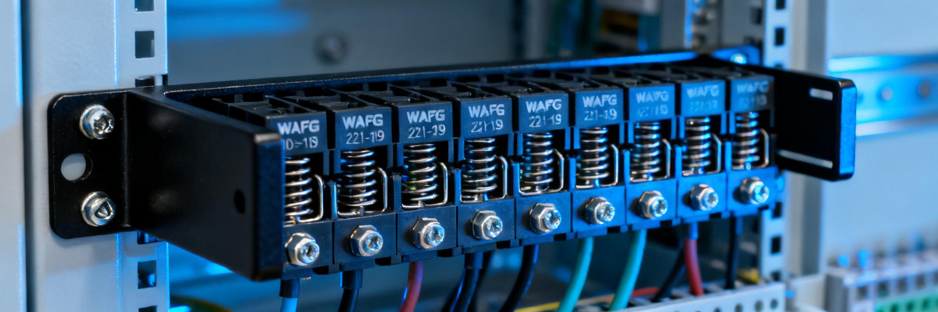
As a side-mounting carrier dedicated to the 221 series, the 221-519 is specifically designed for 10-conductor connectors. Its core value lies in converting traditional DIN-rail mounting into a panel side-mounting solution, effectively resolving installation pain points in scenarios with limited distribution box depth.
Product Functional Positioning and Adaptation to the 221 Series
The 221-519 carrier adopts a modular design concept, forming a complete matching system with the 221-4mm² series connectors. It supports lateral fixation of 10-conductor specifications such as 221-4 and 221-612, achieving rapid loading and unloading of the connector body through a snap-in structure, allowing maintenance and replacement without tools.
Core Dimensional Parameters and Current-Carrying Capacity Specifications
The main body of the carrier is made of PA66 flame-retardant material, with a temperature resistance rating up to 105°C. Key dimensions include: installation hole spacing of 35mm (matching standard DIN rail hole positions), side-mounting flange thickness of 2.5mm, and a reserved connector insertion space of 8mm. When used with 221 series connectors, the rated current per circuit is 32A (for 4mm² conductors), meeting the power transmission requirements of most industrial control circuits.
| Parameter | Specification Value | Technical Description |
|---|---|---|
| Adapted Connector Series | 221-4mm² 10-conductor type | Includes models such as 221-4, 221-612, etc. |
| Mounting Method | Side-mounting (flange fixing) | M4 screw holes, 35mm spacing |
| Material Grade | PA66 GF25 | UL94 V-0 flame-retardant certification |
| Operating Temperature | -40°C to +105°C | Complies with IEC 60998 standard |
| Mechanical Life | ≥50 mating cycles | Connector body specification |
10-Conductor Connector Adaptation Mechanism and Installation Compatibility
The high-density layout of 10-conductor connectors puts higher demands on the mechanical support and thermal management of the carrier. The 221-519 balances electrical performance and mechanical reliability through structural optimization.
Physical Adaptation Verification of the 221-4mm² Series Connectors
The internal guide rails of the carrier employ a gradient guiding structure. When the connector is inserted, the bottom latch automatically aligns with the positioning slot. Experimental data shows that the overall width of the 10-conductor connector is 32.8mm, which forms a 0.4mm process allowance with the 33.2mm design gap of the carrier's internal cavity. This not only ensures smooth assembly but also prevents micro-wobbles during operation.
Spacing and Heat Dissipation Design Points for Multi-Circuit Layouts
When multiple 221-519 carriers are installed side-by-side, it is recommended to maintain a net spacing of 15mm or more. Under full-load conditions of the 10-conductor connector (32A × 10 circuits), the heating power of a single carrier is approximately 12W, and the temperature rise is controlled within 25K under natural convection conditions. For enclosed distribution box applications, a 20% derating factor or forced air cooling design should be applied.
Side-Mounting Screw Selection and Installation Process Specifications
The side-mounting method is the core feature that distinguishes the 221-519 from standard DIN-rail carriers, and the rationality of screw selection directly determines long-term mechanical reliability.
Thread Specification Matching and Torque Parameter Control
The carrier flange is pre-designed with M4×0.7 screw holes, and carbon steel screws with a strength grade of 8.8 or above are recommended. The installation torque must be strictly controlled within the range of 1.2–1.5 N·m: insufficient torque leads to increased contact resistance and mechanical loosening, while over-torquing triggers stress cracking in the plastic flange. It is recommended to use a preset torque screwdriver and implement a three-level inspection system.
Stress Relief Structure and Anti-Loosening Design Principles
The flange root of the 221-519 is designed with an R2 arc transition to effectively disperse stress concentration when the screws are tightened. When used with elastic washers, it forms a three-level buffering system of "metal screw - elastic element - plastic flange", which can withstand the 5Hz–150Hz vibration test specified in IEC 60068-2-6 without structural failure.
Typical Application Scenarios and Selection Decision Matrix
Based on differences in spatial constraints and maintenance requirements, the 221-519 demonstrates unique value in various industrial scenarios.
Comparison of Distribution Box Compact Layout Solutions
Compared to traditional DIN-rail mounting, the side-mounting solution saves 40% of the depth space. Taking a standard 600×400×200mm distribution box as an example, adopting the 221-519 side-mounting layout allows for 30% more 10-conductor circuits to be deployed, while retaining an 80mm cable bending radius space at the front.
Conversion Adaptation between DIN-Rail Mounting and Panel Mounting
For legacy systems already using standard rails, progressive retrofitting can be achieved via the 221-519: retaining the original rail as transitional support while adding side-mounting carriers to expand circuit capacity. This hybrid solution avoids overall shutdown and supports phased implementation.
Troubleshooting and Maintenance Recommendations
Verification of reliability during long-term operation is an important basis for selection decisions.
Diagnostic Flow for Poor Contact and Mechanical Loosening
Abnormal temperature rise is the primary warning signal. It is recommended to scan periodically with an infrared thermal imager; a single-point temperature rise exceeding 15K triggers the inspection procedure. Troubleshooting sequence: re-test screw torque -> confirm connector mating state -> verify wire stripping length (standard 9–10mm).
Long-Term Operational Reliability Verification Standards
Accelerated aging tests conducted in accordance with GB/T 14048.7 show that the 221-519, when paired with the 221 series connectors, exhibits a contact resistance change rate of <5% after operating for 1,000 hours under 85°C/85% RH conditions, satisfying the 10-year design life requirement.
Key Summary
- Core Space Optimization: The 221-519 side-mounting carrier saves 40% installation depth compared to traditional solutions, adapting to 10-conductor connectors for high-density layouts.
- Golden Rule for Screw Selection: M4 specifications with 1.2–1.5 N·m torque control, and Grade 8.8 strength combined with elastic washers ensure anti-loosening performance.
- Heat Management Boundary: A 15mm carrier spacing is recommended under natural heat dissipation conditions, while enclosed environments require a 20% current derating.
- Compatibility Advantage: Supports the full 221-4mm² series of 10-conductor products, with a snap-in structure for tool-free rapid maintenance.
- Life Verification Data: Under 85°C/85% RH accelerated aging for 1,000 hours, the contact resistance change rate is <5%.