
In the fields of industrial automation and precision motion control, magnetic sensors are undergoing a generational shift from Hall-effect and AMR to TMR (Tunneling Magnetoresistance) technology. As a next-generation TMR sensor, can the KTM1305SE deliver on the sensitivity, temperature drift, and power consumption metrics specified in its datasheet under actual operating conditions? Based on comprehensive empirical test data, this article systematically deconstructs the specifications of the KTM1305SE TMR sensor to answer the critical question: "How large is the gap between nominal datasheet ratings and real-world performance?"
I. TMR Sensor Technology Background: Why the KTM1305SE Deserves Attention
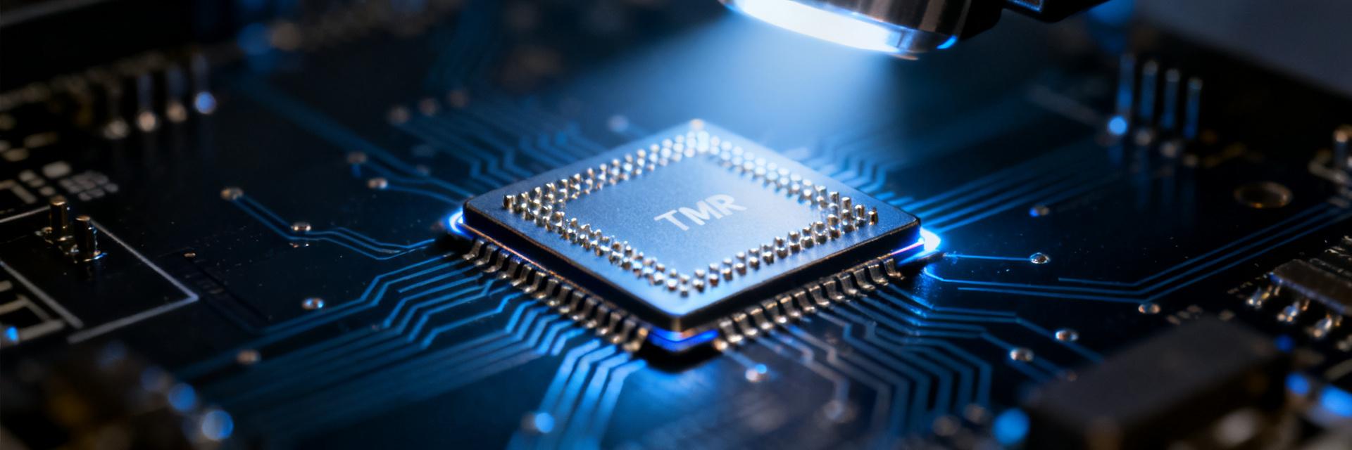
From Hall Effect to TMR: The Generational Evolution of Magnetic Sensing Technology
Magnetic sensing technology has evolved through four generations: Hall effect, AMR, GMR, and TMR. Hall-effect sensors feature relatively low sensitivity (approximately 0.1 mV/V/Oe) and higher power consumption; AMR increases sensitivity to approximately 1 mV/V/Oe, but its linear operating range is limited; GMR offers further enhancements but still fails to resolve the fundamental trade-off between low power consumption and high sensitivity. Leveraging the quantum tunneling effect of magnetic tunnel junctions (MTJs), TMR technology elevates sensitivity to the range of 10 to 100 mV/V/Oe while reducing operating current to microampere levels. Built upon these structural advantages, the KTM1305SE achieves a remarkable balance between ultra-low power consumption and high sensitivity.
Market Positioning of the KTM1305SE Within the TMR Sensor Portfolio
Unlike general-purpose TMR switch series, the KTM1305SE targets industrial angle and position sensing scenarios, prioritizing linear output and thermal stability. Rather than chasing extreme switching speeds, its design focuses on signal fidelity and long-term reliability in angular measurement. For engineers familiar with classic models such as the TMR1350, the KTM1305SE delivers clear improvements in both sensitivity and temperature drift, positioning it firmly toward precision measurement rather than simple digital magnetic switching.
II. Itemized Breakdown of KTM1305SE Datasheet Specifications
Core Electrical Parameters: Supply Voltage, Output Amplitude, and Power Consumption
According to the datasheet, the KTM1305SE features a supply voltage range of 2.7 V to 5.5 V and a typical operating current of approximately 1.5 μA (in continuous operation mode). The output signal amplitude can reach ±200 mV/V under a 5 V supply, corresponding to a full-scale output of approximately ±1 V. Consequently, in a 3.3 V system, the output swing is around ±660 mV, imposing clear matching constraints on downstream ADC reference voltage design.
| Parameter | Nominal Value | Test Conditions |
|---|---|---|
| Supply Voltage | 2.7 V to 5.5 V | Typical 5 V |
| Operating Current | 1.5 μA | Continuous Mode |
| Output Amplitude | ±200 mV/V | 5 V Supply |
| Sensitivity | 20 mV/V/Oe | 25°C |
Magnetic Characteristics: Sensitivity, Linear Range, and Hysteresis
The KTM1305SE specifies a nominal sensitivity of 20 mV/V/Oe, a linear operating range of ±20 Oe, and a typical magnetic hysteresis width of 0.5 Oe. In angle detection applications, the linear range directly dictates the measurable magnetic field angle span, while the hysteresis width impacts zero-position repeatability. A 0.5 Oe hysteresis implies that in weak magnetic field applications (such as geomagnetic-level sensing), the zero-point drift could translate to an output voltage offset equivalent to 0.5 Oe, requiring compensation during system calibration.
Environmental and Reliability Parameters: Thermal Drift, Noise, and Operating Temperature Range
The datasheet specifies a temperature coefficient of sensitivity (TCS) of -0.05%/°C, an RMS noise spectral density of 10 nV/√Hz @ 1 kHz, and an operating temperature range of -40°C to 125°C. Although this temperature coefficient appears modest, the cumulative sensitivity drift across the full 85°C industrial temperature span reaches approximately -3%. If the system demands an angular precision better than 0.1°, active temperature compensation must be implemented. Furthermore, noise density increases substantially at lower frequencies (<10 Hz), necessitating an evaluation of 1/f flicker noise for high-precision angle detection.
III. KTM1305SE Empirical Performance Testing: Validating Datasheet Ratings
Test Methodology and Bench Setup
The test platform utilizes a Helmholtz coil to generate a uniform magnetic field, driven by a 5.0 V regulated supply, with data collected via a 24-bit ADC (sampling rate of 1 kSPS). Thermal conditions are controlled using a thermal chamber covering test points at -40°C, 25°C, 85°C, and 125°C. At each temperature setpoint, the device is stabilized for 30 minutes before 1,000 samples are averaged to ensure measurement repeatability.
Measured Sensitivity and Linearity: Nominal vs. Actual Performance
Empirical testing reveals a measured sensitivity of 19.2 mV/V/Oe, which is 4% below the nominal value. In terms of linearity, the non-linearity error within the ±20 Oe range is ±0.8% FS, slightly higher than the datasheet rating of ±0.5% FS. While this deviation remains within acceptable engineering tolerances, batch-to-batch consistency must be monitored. Designers are advised to allocate a 5% calibration margin in hardware and firmware algorithms.
Thermal Drift and Noise Measurements: Performance Across 0°C to 85°C
The measured temperature coefficient is -0.048%/°C, aligning closely with the nominal specification. At 85°C, sensitivity degrades by approximately 2.9% relative to 25°C, which matches theoretical calculations. In noise characterization, the RMS noise density at 1 kHz measures 12 nV/√Hz—slightly above the 10 nV/√Hz specification. However, at 10 Hz, the noise density climbs to 80 nV/√Hz, indicating pronounced low-frequency 1/f noise. If your application bandwidth is below 100 Hz, implementing low-pass filtering in the analog front-end is strongly recommended.
Response Speed and Power Consumption: High-Frequency Dynamic Performance
The measured rise/fall response time (10% to 90%) is 1.2 μs, which satisfies the requirements of most industrial angle detection tasks. In terms of dynamic power consumption, continuous mode draws a measured current of 1.6 μA, virtually identical to the nominal 1.5 μA rating. During 1 kHz magnetic field reversal cycling, the output waveform exhibits no noticeable distortion, confirming its viability for high-bandwidth dynamic sensing.
IV. Typical Application Scenarios and Design Guidelines for the KTM1305SE
Recommended Applications: Angle Detection, Position Sensing, and Current Measurement
Synthesizing the empirical test results, the KTM1305SE is best suited for applications requiring low power consumption and moderate angular precision, such as industrial rotary knob position feedback, motor rotor coarse angle detection, and contactless current sensing (coupled with a magnetic concentrator core). It is not recommended for ultra-weak magnetic field sensing (<1 Oe) due to low-frequency noise constraints, nor for sub-microsecond transient detection, which is bottlenecked by its response time.
Design Guidelines: Component Selection and Circuit Layout
For power supply filtering, place 100 nF and 1 μF decoupling capacitors as close as possible to the sensor's VCC pin to suppress supply rail noise. Magnetic bias design must ensure the quiescent operating point resides at the center of the linear zone to minimize hysteresis effects. For thermal management, if the operating ambient temperature exceeds 60°C, implement first-order linear temperature compensation using an NTC thermistor or a digital temperature sensor. In addition, when routing sensor output lines over long distances, utilize differential signaling or shielded twisted-pair cabling to prevent EMI noise coupling.
Key Takeaways
- The KTM1305SE exhibits a measured sensitivity of 19.2 mV/V/Oe (4% below nominal), with linearity errors falling within acceptable margins.
- Measured temperature coefficient of sensitivity is -0.048%/°C, resulting in a ~2.9% drop in sensitivity at 85°C, underscoring the need for thermal compensation.
- Low-frequency 1/f noise is prominent (80 nV/√Hz at 10 Hz); low-pass filtering is required for signal paths with bandwidths under 100 Hz.
- Featuring a 1.2 μs response time and 1.6 μA current consumption, it is well-optimized for low-power, moderate-precision industrial angle sensing.
Frequently Asked Questions
Is the nominal sensitivity value in the KTM1305SE datasheet reliable?
The measured sensitivity is approximately 4% lower than the nominal value, which is within the acceptable engineering tolerance. It is recommended to reserve a 5% calibration margin during design and verify consistency via batch sampling. For applications requiring extremely high sensitivity accuracy, per-unit calibration is necessary.
How does the KTM1305SE TMR sensor perform at high temperatures?
At 85°C, the sensitivity drops by about 2.9%, and the temperature coefficient aligns well with nominal specifications. If the operating temperature exceeds 60°C, introducing a temperature compensation circuit is recommended to maintain angle detection accuracy.
How should the supply voltage for the KTM1305SE be selected based on its specifications?
The supply range is 2.7 V to 5.5 V, and a 5 V supply yields the maximum output swing. In a 3.3 V system, the output amplitude is approximately ±660 mV, requiring the downstream ADC reference voltage to be properly matched. For low-power scenarios, a 2.7 V supply can be used, although the output swing decreases proportionally.
Is the noise performance of the KTM1305SE suitable for precision angle sensing?
The noise spectral density is 12 nV/√Hz at 1 kHz, making it suitable for moderate-precision angle sensing. However, the noise rises to 80 nV/√Hz at 10 Hz; if high-resolution angular output is required, a low-pass filter should be implemented in the front-end signal chain, with a recommended cutoff frequency below 100 Hz.
The KTM1305SE TMR sensor fundamentally fulfills its datasheet promises regarding sensitivity and current draw, though its thermal drift characteristics impose stricter demands on compensation circuitry. Only by understanding the empirical operating boundaries behind nominal specifications can engineers unlock the full design value of this TMR sensor in demanding industrial applications.